AUGUR Digital Twin for Robotics

INTRODUCTION
PULSAR HRI is not a motor company; we are a robotics company, deeply rooted in fundamental robotics research, that has chosen to develop best-in-class enablers and tools, as we see these as essential steps towards creating more capable robots. To demonstrate the full potential of our technology, we are developing a series of robotic platforms (the first of which is a robotic arm).
The design of PULSE robotic arm demonstrator has systematically relied on a high fidelity virtual model that integrates both the manipulator geometry and dynamic models, including AUGUR, the digital twin of PULSAR actuators. This model-based approach has made it possible to explore alternative configurations, estimate performance and detect limitations before manufacturing critical components, thereby reducing technical risk and the number of hardware iteration cycles.
This WP describes how the virtual model has been used throughout the design process: from the generation of the “raw” model (URDF) and its conversion into simulation models, to its use in the evaluation of performance metrics and in the preparation of the topological optimisation of structural parts.

ROLE OF THE VIRTUAL MODEL IN THE DESIGN PROCESS
The virtual model of the PULSE arm acts as a central node connecting:
- The definition of design requirements and constraints (kinematic chain, actuator catalogue, bracket library).
- The evaluation modules (e.g. masses, workspace, payloads, and other metrics).
- The dynamic simulation tools (MuJoCo), where trajectories, loads and configurations are tested.
- The structural and mass optimisation (topological optimisation of brackets, CAD model).
- The robot control and its validation (use of the actuator digital twin and the arm model in control loops and trajectory tests).
In practice, the virtual model closes the loop between requirements, design, simulation and redesign far more quickly and cheaply than iterating exclusively on hardware.
GENERATION OF THE VIRTUAL MODEL OF THE ARM
Definition of the kinematic chain and components
The kinematic chain of the arm was defined with 4 degrees of freedom, in an arrangement analogous to a human arm (base–shoulder–elbow–wrist).
On this basis the following were incorporated:
- PULSE actuators:
- PULSE115: higher‑torque actuators, 60Nm peak torque.
- PULSE98: more compact and lightweight actuators, 30Nm peak torque, initially more suitable for distal joints.
- Links and brackets:
- Supports defined by geometric parameters (lengths, thicknesses, diameters, etc.), maintaining kinematic and assembly consistency.
These parts were combined to obtain a number of candidate configurations:
| Config. # | J1 | J2 | J3 | J4 |
| 1 | PULSE115 | PULSE115 | PULSE115 | PULSE115 |
| 2 | PULSE98 | PULSE98 | PULSE98 | PULSE98 |
| 3 | PULSE115 | PULSE98 | PULSE98 | PULSE98 |
| 4 | PULSE115 | PULSE115 | PULSE98 | PULSE98 |
| n | … | … | … | … |
INTEGRATION OF THE DIGITAL TWIN OF THE ACTUATORS
A distinctive aspect of the project is the use of a low‑level digital twin (AUGUR) for the PULSE actuators:
These digital twin models the actuator’s electromechanical characteristics (including torque and current constants, nominal and peak limits, and internal losses) while also capturing its behaviour under different torque, speed, or position control laws. In addition, it reproduces the internal actuator dynamics that emerge during representative tasks, providing a faithful and comprehensive virtual counterpart to the physical system.
In the context of the arm, the virtual model connects to AUGUR in several ways:
- Actuator design: the same Digital Twin is used to optimise the actuators.
- Payload and power assessment: from the joint forces/torques calculated in the MuJoCo model, currents and power consumption per actuator can be inferred.
- Control testing: when executing trajectories (for example the diagonal line), the response of the actuators under different gains is simulated, anticipating stability, tracking errors and saturations.
The virtual model of the arm is therefore not just a kinematic skeleton; it is an integrated electro‑mechanical simulation platform.
USE OF THE VIRTUAL MODEL FOR PERFORMANCE EVALUATION
Static configurations and payloads
Starting from the URDF/XML, a family of 36 static configurations distributed across the workspace was defined (documented on the TNO page). For each configuration and end‑effector load (0, 1, 2 and 3 kg) the following were computed:
- Required torque at each joint.
- Estimated current and total power on the DC bus.
- Margins with respect to nominal and peak actuator torque.
These studies led to the following conclusions:
- The arm can handle 1 kg of payload comfortably in all configurations.
- For payloads in the 2–3 kg range, the requirements approach or slightly exceed the nominal torque in extreme cases but remain within the peak limits and are therefore considered acceptable. This is particularly true given that, at this point, the URDF still relies on non-optimised brackets, which leads to conservative mass estimates. Also, the nominal and peak definitions for the custom actuators are themselves conservative.
This analysis was key to determining that the configuration 2×PULSE115 + 2×PULSE98 is suitable for a target payload of around 3 kg to be operated under nominal conditions (i.e. actuators can provide nominal torque indefinitely without active cooling).
Dynamic trajectories and ISO 9283 metrics
The virtual model has also been employed to prepare and test dynamic trajectories with the dual purpose of verifying and tuning the control layer (using proof-of-concept implementations built upon actuator digital twins) and computing standardized accuracy and tracking metrics in accordance with ISO 9283.
Through these simulations, it becomes possible to estimate the ranges of speed and acceleration within which the arm maintains acceptable accuracy, to identify payload–speed combinations that may demand more advanced control strategies or performance limitations.
USE OF THE VIRTUAL MODEL FOR STRUCTURAL OPTIMISATION
A model was created in MuJoCo where force and torque sensors at the centre of mass of each component. This model has been used to:
- Obtain the map of static loads on each bracket component under multiple configurations and end‑effector loads.
- Identify, for each part, the worst‑case load scenario (force and moment peaks).
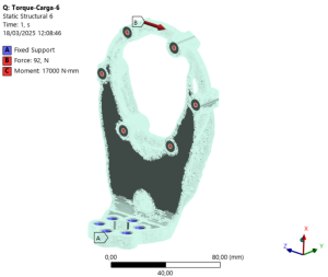
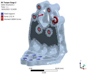
Structural load evaluation:

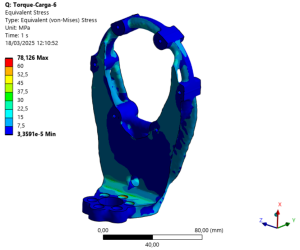
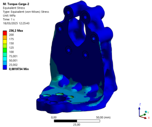
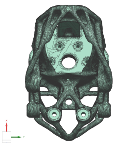
With this data a topological optimisation of the CAD supports was carried out, where:
- The worst‑case static loads were used as applied forces, scaled by a safety factor.
- The objective was to reduce the mass of each bracket, aiming at a reduction of approximately 85% of its original mass.
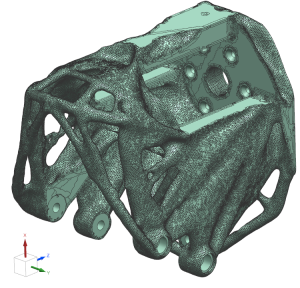
- The resulting designs, with “organic” geometries suitable for metal additive manufacturing, are then reintegrated into the design loop:
In summary, the virtual model has provided the quantitative foundation needed to dimension the structure appropriately, justify the selection of both the material and the manufacturing process (specifically aluminium combined with metal 3D printing) and minimise the overall mass while ensuring that the required structural integrity is fully preserved.
CONTRIBUTION OF THE VIRTUAL MODEL TO THE SIM2REAL BRIDGE
The intensive use of the virtual model in the design of the Humbot arm has had concrete impacts on the Sim2Real transition:
- Fewer physical iterations: The first 3D‑printed mock‑up and subsequent prototypes were derived from a design already validated in simulation, reducing “surprise” corrections during assembly.
- Architecture and configuration decisions: The choice of actuator combinations and link lengths was based on simulations of payload, workspace and power consumption.
- Preparation of test campaigns on the evaluation bench: Definition of the metrics and trajectories that will also be applied to the physical arm, enabling direct Sim vs Real comparison.
- Validation of the design: The arm serves as a use‑case where the same metrics and evaluation modules apply to both the virtual model and the physical prototype, closing the validation loop.

CONCLUSIONS
The design of the PULSE arm has not followed a traditional CAD-to-manufacturing pipeline; instead, it has deliberately integrated a rich virtual model that combines the mechanical description of the system (URDF/XML), high-fidelity actuator digital twins, and advanced dynamic and structural simulation tools.
This integrated approach has made it possible to dimension the arm for representative loads and tasks, optimise the mass and topology of the brackets before any physical manufacturing takes place, and prepare system evaluation and control within a safe and repeatable virtual environment. Overall, the virtual model forms the core of the project’s Sim2Real strategy and will remain essential both throughout the experimental validation phases and in future design iterations of the manipulator.